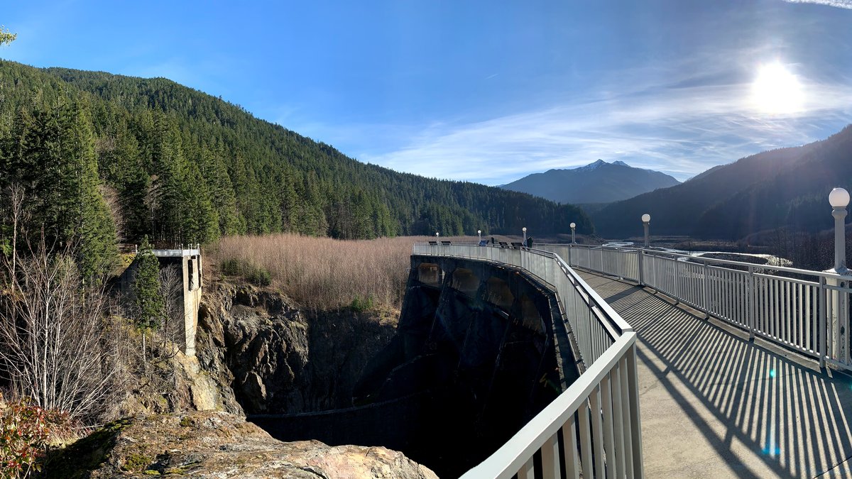
Dams represent some of the most monumental and consequential civil engineering feats in human history. By impounding millions of cubic meters of water, mega-dams generate renewable hydroelectric gigawatts, mitigate catastrophic seasonal floods, irrigate agricultural breadbaskets, and supply potable water to thirsty megacities. However, holding back the immense hydrostatic weight of an artificial sea demands uncompromising structural rigor, geotechnical precision, hydraulic fluid mastery, and delicate environmental stewardship.
Core Hydraulic Realities
- Hydrostatic Equilibrium: A dam is a barrier in constant equilibrium against water pressure that increases linearly with depth, exerting millions of tonnes of horizontal shearing force and foundation overturning moments.
- Structural Taxonomy: Dam design conforms strictly to valley geology—massive gravity dams rely on raw deadweight; arch dams exploit geometric curvature to transfer loads into canyon walls; and embankment dams utilize compacted earth and rockfill to spread load over alluvial plains.
- Spillway Supremacy: A dam can survive almost any structural loading except uncontrolled overtopping. The spillway is the safety valve of the reservoir, engineered to safely eject catastrophic 10,000-year flood volumes at supersonic velocities without eroding the dam toe.
- Hydraulic Energy Conversion: Hydroelectric dams serve as the world’s premier grid-scale energy storage batteries, utilizing pumped-storage hydropower (PSH) to balance intermittent solar and wind grids within milliseconds.
Table of Contents
- 1. The Four Primary Structural Classifications of Dams
- 2. Hydrodynamics and Dam Stability Vectors
- 3. Hydraulic Control Systems: Spillways and Energy Dissipation
- 4. Hydroelectric Power Generation: Turbines and Penstocks
- 5. Environmental Stewardship and Ecological Mitigation
- 6. Structural Health Monitoring & Dam Safety Telemetry
- 7. Frequently Asked Questions (FAQ)
- 8. Conclusion: The Enduring Mastery of Hydraulic Civil Systems
1. The Four Primary Structural Classifications of Dams
Selecting the typology of a dam is not an aesthetic choice; it is dictated by the topographic profile of the river valley, the mechanical bearing capacity of the foundation rock, and the availability of local construction materials.
To examine how ancient civilizations first mastered gravity diversion and irrigation canals, read our historical retrospective on The Epic History of Human Civil Infrastructure.
| Dam Classification | Structural Load Mechanism | Optimal Valley Profile | Signature Global Example |
|---|---|---|---|
| Gravity Dam | Pure deadweight resists horizontal water sliding & overturning | Wide or narrow valleys with solid bedrock foundations | Three Gorges Dam (China) / Grand Coulee (USA) |
| Arch Dam | Arch curvature transmits water load laterally into canyon walls | Narrow, deep canyons with sound, unyielding rock abutments | Hoover Dam (Arch-Gravity) / Enguri Dam (Georgia) |
| Buttress Dam | Upstream face supported by triangular vertical concrete buttresses | Wide valleys with moderate rock strength; saves concrete | Daniel-Johnson Dam (Canada) / Itaipu (Segmented) |
| Embankment Dam | Compacted earth/rockfill with an impermeable clay/concrete core | Broad alluvial valleys with deep sediment beds | Nurek Dam (Tajikistan) / Tarbela Dam (Pakistan) |
1. Concrete Gravity Dams
A concrete gravity dam is essentially a triangular wedge of solid mass concrete. Its basic premise is mechanical brute force: the downward gravitational force of the concrete’s enormous self-weight must be sufficiently large to hold the structure down against two primary destabilizing forces:
- Sliding: The horizontal hydrostatic force pushing the dam downstream along its foundation contact plane. The Shear Friction Factor of Safety must typically exceed 2.0 to 3.0.
- Overturning: The rotational moment around the downstream toe caused by horizontal water pressure. To prevent the upstream heel of the dam from lifting and cracking, the resultant of all forces must fall within the middle third of the dam base under all operating conditions.
Modern gravity dams are frequently built using Roller-Compacted Concrete (RCC). Unlike traditional wet-poured mass concrete, zero-slump RCC is transported by dump trucks, spread by bulldozers in 30 cm lifts, and compacted with vibratory rollers. This slashes construction timelines from a decade to two or three years while dramatically reducing hydration heat.
2. Arch Dams: Thin-Shell Geometric Mastery
Where gravity dams rely on volume, arch dams rely on mathematical geometry. An arch dam curves upstream into the reservoir. As water presses against the convex face, the concrete is placed into continuous pure axial compression. This compressive force travels laterally along the arch ring into the natural rock walls (abutments) of the canyon gorge. (This behaves identically to the compression paths seen in Arch Bridge Typologies).
Modern arch dams are constructed as double-curvature (thin-shell) structures—meaning they curve both horizontally across the canyon and vertically from base to crest. This double-curved shape (resembling a contact lens) ensures that bending moments are virtually zero throughout the height of the dam, reducing concrete consumption by up to 60% compared to an equivalent gravity dam. However, arch dams require virtually indestructible, fault-free granite or basalt canyon walls capable of absorbing tens of thousands of tonnes of lateral thrust.
3. Embankment Dams (Earth-Fill and Rockfill)
Embankment dams account for over 70% of the world’s major dams because they can be founded on softer alluvial soils that would crack or settle under rigid concrete dams. They are massive trapezoidal mounds constructed from locally excavated materials:
Internal Zonation of an Embankment Dam
Impermeable Clay Core: A central vertical or inclined core constructed of dense, highly plastic clay compacted at optimum moisture content. The clay particles seal tightly, preventing water from percolating through the dam.
Granular Filter & Transition Zones: Flanking the clay core on both sides are precision-graded sand and fine gravel transition zones. These prevent clay particles from washing away (“internal piping”) if micro-fissures develop.
Structural Rockfill Shoulders: Massive outer slopes constructed of heavy blasted rock boulders, providing weight, structural slope stability, and protection against shear failure.
Upstream Rip-Rap: Heavy, interlocking armor rocks (or interlocking concrete dolosse) placed on the upstream water slope to prevent reservoir wind waves from eroding the embankment.
CFRD (Concrete-Faced Rockfill Dam): An alternative modern design where the impermeable barrier is an engineered reinforced concrete slab cast directly onto the upstream slope face, eliminating the internal clay core entirely.
2. Hydrodynamics and Dam Stability Vectors
Civil engineers must perform complex finite element equilibrium calculations to balance every force vector acting upon the dam body:
1. Hydrostatic Pressure
Static water pressure acts perpendicular to the upstream face, increasing linearly with depth ($P = \rho g h$). The total horizontal thrust force ($F_H$) per unit width is calculated as:
where $\gamma_w$ is the unit weight of water ($9.81\text{ kN/m}^3$) and $H$ is water depth. This force acts at a centroid located at a height of $H/3$ from the base, exerting an enormous overturning leverage arm.
2. Uplift Pressure: The Silent Foundation Destroyer
Water does not just push horizontally; reservoir head forces water into the microscopic fissures and pores of the rock foundation beneath the dam base. This seeped water exerts a vertical uplift pressure acting upward against the base, effectively “floating” the dam and canceling out its stabilizing self-weight.
To combat uplift, engineers deploy a two-tiered defense:
- Grout Curtains: Deep holes are drilled deep into the foundation rock near the upstream heel. Microfine cement grout is injected under high pressure to fill all rock cracks, creating an impermeable subterranean barrier.
- Drainage Galleries & Relief Wells: Hollow inspection tunnels run along the base inside the dam. Vertical drainage holes drilled downstream of the grout curtain intercept any remaining seepage water, safely discharging it into the tailrace and collapsing uplift pore pressure.
3. Dynamic Seismic & Hydrodynamic Surge (Westergaard Effect)
During an earthquake, ground shaking accelerates the dam against the reservoir water mass. Because water is practically incompressible, this creates an instantaneous hydrodynamic shockwave known as Westergaard’s hydrodynamic pressure, adding immense cyclic lateral shear forces to the dam’s upstream face.
3. Hydraulic Control Systems: Spillways and Energy Dissipation
Overtopping is fatal to embankment dams (washing away the fill in minutes) and dangerous to concrete dams (scouring the foundation toe). Spillways are hydraulic safety valves engineered to bypass floodwaters safely.
Spillway Typologies
- Ogee (Overflow) Crest Spillway: The profile of the spillway weir is hydrodynamically shaped to match the exact lower nappe of a freely discharging sheet of water. This prevents negative pressure zones that cause destructive cavitation—the implosion of vapor bubbles that can chew through meters of solid reinforced concrete.
- Morning Glory (Bell-Mouth) Spillway: A colossal circular submerged concrete funnel located inside the reservoir (such as the Monticello Dam spillway in California). When the reservoir reaches flood stage, water cascades down the central vertical shaft and discharges through a horizontal tunnel beneath the dam.
- Stepped Chute Spillway: Concrete steps built into the downstream spillway face aerate the cascading water flow, dissipating over 50% of kinetic energy before the water even reaches the river below.
Energy Dissipators: Taming Kinetic Energy
Water plunging down a 150-meter spillway chute reaches speeds exceeding 150 km/h (40+ m/s), carrying millions of horsepower of destructive energy. Left unmitigated, this kinetic jet would excavate a massive crater at the base, undermining the dam foundations. Engineers dissipate this energy using:
- Hydraulic Jump Stilling Basins: The high-velocity supercritical flow is forced through a concrete basin equipped with baffle blocks and an end sill, forcing a turbulent hydraulic jump that transitions the water into low-velocity subcritical flow.
- Flip Buckets and Ski Jumps: Curved upward ramps at the end of the chute that launch the high-velocity water jet hundreds of meters through the air into a deep plunge pool far downstream from the dam toe.
4. Hydroelectric Power Generation: Turbines and Penstocks
Mega-dams transform gravitational potential energy into clean, dispatchable electrical power:
Turbine Selection by Hydraulic Head
- Francis Turbines (Medium to High Head: 40m–600m): The world’s most versatile mixed-flow reaction turbine. Water enters radially through a spiral scroll case and discharges axially downward, spinning runners with efficiencies exceeding 95%. Used in Hoover and Three Gorges dams.
- Pelton Wheels (Ultra-High Head: 300m–1,800m): Impulse turbines deployed in steep mountainous canyons. High-pressure water shoots through precision needle nozzles at supersonic velocity, striking dual-cupped buckets mounted around the wheel rim.
- Kaplan Turbines (Low Head: 5m–70m): Propeller-style turbines with computer-controlled adjustable blades, optimizing power generation on wide, high-volume lowland rivers.
- Pumped-Storage Hydropower (PSH): The ultimate renewable battery. During periods of excess grid energy (low demand, high solar/wind production), reversible pump-turbines pump water from a lower reservoir back up into an upper reservoir. When peak demand strikes, water is released downward to generate instant gigawatts within 60 seconds. (Hydraulic penstocks and turbine caverns rely on specialized tunneling methods described in our guide on Tunnels and Underground Caverns).
5. Environmental Stewardship and Ecological Mitigation
Historically, dams were constructed with little regard for downstream ecosystems, blocking migratory fish runs, trapping fertile river silt, and altering water temperatures. Modern environmental regulations require extensive mitigation infrastructure:
- Fish Passage Infrastructure: Incorporating stepped pool-and-weir fish ladders, Archimedes screw lifts, and pressurized fish elevators that allow salmon, hilsa, and sturgeon to navigate upstream past dam barriers.
- Sediment Management: Reservoirs naturally trap river silt, causing long-term reservoir capacity loss while starving downstream deltas of natural sand. Engineers design deep bottom-outlet sluices and sediment bypass tunnels to periodically flush accumulated sediment downstream during monsoon freshets.
- Selective Withdrawal Intakes: Multi-level reservoir intake towers allow operators to blend warm surface water with cold, oxygen-rich deep water, ensuring downstream river discharges match seasonal natural temperatures and sustain aquatic habitats.
6. Structural Health Monitoring & Dam Safety Telemetry
Given the catastrophic downstream consequences of a breach, dam safety relies on multi-redundant structural monitoring networks:
- Inverted Plumb-Lines (Pendulums): Heavy stainless-steel wires suspended from the dam crest down into deep foundation anchor wells. Optical micrometers measure deflections of the dam crest relative to deep bedrock with sub-millimeter precision.
- Piezometer Grids: Vibrating-wire piezometers embedded across the foundation plane to monitor hydrostatic pore pressure and verify that drainage relief holes remain unblocked.
- Satellite InSAR Radar Interferometry: Synthetic Aperture Radar satellites scan dam crests from orbit every 6 to 12 days, identifying millimeter-scale seasonal thermal expansion or foundation settlement patterns over entire reservoir regions.
7. Frequently Asked Questions (FAQ)
Q1: How do engineers prevent mass concrete in mega-dams from cracking during curing?
Hydration of Portland cement generates intense exothermic heat. In a mega-dam, this heat cannot escape, creating internal temperatures exceeding $70^\circ\text{C}$ that would cause catastrophic thermal cracking. To prevent this, engineers substitute cement with fly ash/slag, pre-cool aggregates with shaved ice, pour concrete in small modular blocks separated by contraction joints, and circulate chilled water through embedded serpentine cooling pipes inside the concrete for months.
Q2: What is “internal piping” in an earthen dam?
Internal piping is the leading cause of embankment dam failure. It occurs when seepage water erodes fine soil particles from inside the dam, creating a small internal pipe-like void. As more water rushes through the pipe, erosion accelerates exponentially until the entire dam collapses.
Q3: How much power does the world’s largest dam produce?
China’s Three Gorges Dam on the Yangtze River possesses an installed capacity of 22,500 Megawatts (22.5 GW) across 34 massive turbine units, generating over 100 billion kilowatt-hours of clean electricity annually—equivalent to burning 30 million tonnes of coal.
8. Conclusion: The Enduring Mastery of Hydraulic Civil Systems
Dams and hydraulic infrastructure are unmatched in their scale, societal utility, and structural consequence. By taming seasonal floods, providing clean baseload and storage power, and delivering irrigation water to arid regions, dams have reshaped the geography of human civilization. As climate change increases hydrological volatility with unprecedented droughts and super-floods, the civil engineering principles of dam stability, spillway hydraulics, and ecological balance will remain essential pillars of global resilience.



2 thoughts on “Mastering Water Power: The Engineering, Hydraulics, and Ecosystems of Mega Dams and Hydraulic Infrastructure”