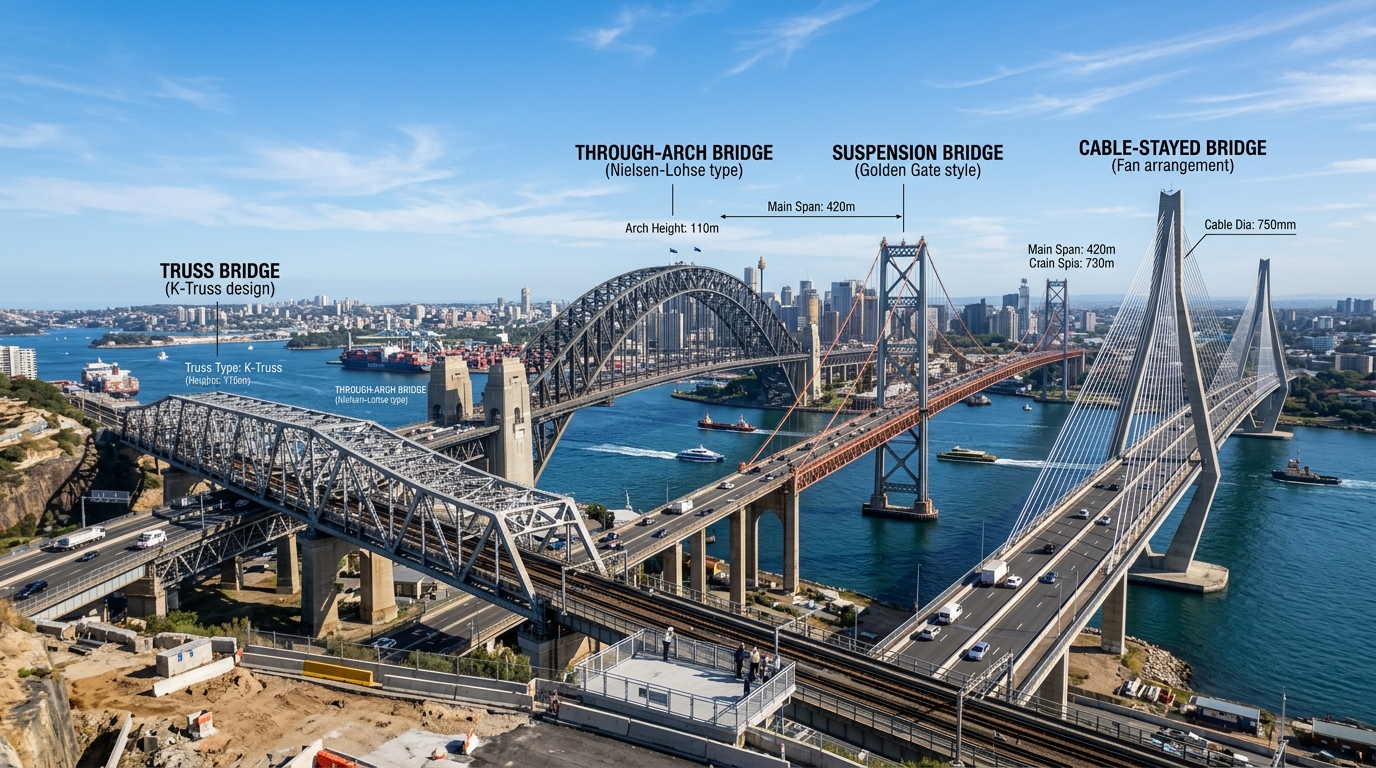
Every bridge in the world is a physical triumph over gravity, distance, and environmental adversity. While each crossing is custom-tailored to its specific geographical site, all bridges conform to a defined set of structural typologies. Selecting the optimal bridge type is among the most consequential decisions a civil engineer can make, dictating structural load pathways, material consumption, seismic vulnerability, aesthetic identity, and lifecycle expenditure over centuries.
Essential Structural Principles
- Load Path Dichotomy: Bridge typology dictates whether dead and live forces are resolved primarily through bending flexure (beam/girder), direct axial compression (arch), triangulated axial tension/compression (truss), or pure tensile cable suspension.
- Span Capacity Hierarchy: Beam bridges dominate short spans (< 80m); trusses and arches excel in medium spans (80m–400m); cable-stayed systems dominate intermediate long spans (200m–1,100m); and suspension bridges hold the absolute crown for ultra-long spans (1,000m–2,000m+).
- Geotechnical Dictation: The underlying geology strictly governs typology. True arches require monolithic bedrock to resist massive horizontal thrust, while cable-stayed bridges can tolerate softer alluvial soils using deep friction pile groups.
Table of Contents
- 1. The Fundamental Typology Matrix
- 2. Beam and Girder Bridges: The Workhorses of Civil Networks
- 3. Truss Bridges: The Geometry of Triangulation
- 4. Arch Bridges: Ancient Mastery and Modern Axial Thrust
- 5. Cantilever Bridges: The Balanced Equilibrium
- 6. Cable-Stayed Bridges: Geometric Elegance and Modern Efficiency
- 7. Suspension Bridges: Conquering the Longest Spans on Earth
- 8. Movable Bridges: Navigating Complex Waterways
- 9. Engineering Selection Criteria: How Engineers Choose a Bridge Type
- 10. Frequently Asked Questions (FAQ)
- 11. Conclusion: The Art and Engineering of Structural Form
1. The Fundamental Typology Matrix
In structural mechanics, bridge classification is determined by the internal stress distribution inside the primary load-bearing members. When gravity acts upon a vehicle crossing a bridge deck, that downward force must ultimately reach the solid earth. How that force travels—and the geometric configuration of the members resisting it—defines the seven major bridge types.
For a foundational understanding of overall transportation networks and structural health monitoring, see our macro-guide on Bridges & Modern Civil Infrastructure.
| Bridge Type | Primary Internal Force | Economic Span Range | Signature Global Example |
|---|---|---|---|
| Beam & Girder | Bending (Flexure) & Shear | 10 m – 120 m (up to 250m for box girders) | Lake Pontchartrain Causeway (USA) |
| Truss Bridge | Triangulated Axial Tension & Compression | 50 m – 350 m | Ikitsuki Bridge (Japan) / Astoria-Megler (USA) |
| Arch Bridge | Pure Axial Compression & Thrust | 40 m – 550 m | Sydney Harbour (Australia) / Chaotianmen (China) |
| Cantilever Bridge | Balanced Moment Cantilevers & Suspended Span | 100 m – 550 m | Forth Bridge (Scotland) / Quebec Bridge (Canada) |
| Cable-Stayed | Tension in Stays, Axial Compression in Pylons/Deck | 200 m – 1,104 m | Millau Viaduct (France) / Russky Bridge (Russia) |
| Suspension Bridge | Pure Tension in Main Cables, Compression in Towers | 500 m – 2,500+ m | 1915 Çanakkale (Turkey) / Golden Gate (USA) |
| Movable Bridges | Kinematic Mechanical Pivot / Counterweight | Site-specific waterway navigation | Tower Bridge (London) / Erasmusbrug (Netherlands) |
2. Beam and Girder Bridges: The Workhorses of Civil Networks
Beam bridges represent the simplest and most widespread structural type on the planet. Comprising horizontal beams supported at each end by substructure piers or abutments, they make up more than 75% of global highway overpasses and viaducts.
Structural Mechanics of Beam Action
When vertical load is applied to a simple beam between two supports, the member bends downward. This flexure creates a dual-stress profile across the beam’s neutral axis:
- The upper fibers of the beam are pushed together in compression.
- The lower fibers are stretched apart in tension.
- The central web experiences vertical and horizontal shear stress.
Key Girder Sub-Types
1. Prestressed and Post-Tensioned Concrete Girders
Concrete is naturally strong in compression but catastrophically brittle under tension. In prestressed concrete girders (such as standard AASHTO I-girders or bulb-tee sections), high-strength steel strands are stretched inside formwork before the concrete is poured. Once cured, the steel tension is released, pre-compressing the lower concrete zone. Under live vehicular loads, this pre-compression offsets the tensile forces, preventing cracking and extending spans up to 50 meters.
2. Steel Plate Girders
Fabricated by welding heavy steel plates into an “I” cross-section. For medium spans (30m to 90m), variable-depth steel plate girders feature deeper webs over intermediate piers where negative bending moments are highest, optimizing steel weight.
3. Segmental Concrete and Steel Box Girders
For curved highways and long spans (100m to 250m), box girders provide immense torsional resistance. These hollow, trapezoidal tubes are constructed using balanced cantilever erection: precast segments are hoisted into place and stitched together using internal longitudinal post-tensioning tendons, eliminating the need for temporary ground falsework.
3. Truss Bridges: The Geometry of Triangulation
Truss bridges achieved monumental dominance during the 19th-century railway expansion and remain unmatched in material efficiency for heavy rail freight corridors. For a detailed chronicle of how early iron truss bridges sparked the modern railway age, explore our retrospective on The Epic History of Human Civil Infrastructure.
The Principle of Rigid Triangles
A polygon with four or more sides can easily distort when subjected to corner forces. However, a triangle is inherently rigid: its geometry cannot be altered without physically deforming or fracturing one of its sides. Truss bridges assemble interconnected linear structural members into an interconnected network of triangles. Because members are theoretically connected at frictionless pinned joints (or rigid gusset plates in modern practice), external loads are resolved almost exclusively as pure axial tension or pure axial compression, eliminating bending moments inside individual members.
Historic and Modern Truss Configurations
- Pratt Truss: Identified by vertical members under compression and diagonal members that slope downward toward the center under tension. Since steel members can resist tension far more efficiently without buckling, the Pratt design allowed 19th-century builders to use lighter diagonal iron bars.
- Howe Truss: The inverse of the Pratt truss. Vertical members are in tension (often threaded steel rods) while diagonal members are in compression (historically timber or cast iron). Excellent for composite timber-steel construction.
- Warren Truss: Composed of alternating equilateral or isosceles triangles without vertical struts (or with optional verticals to reduce floor beam spacing). Diagonals alternate between tension and compression as loads traverse the span, creating an exceptionally clean, symmetrical, and efficient structure.
- K-Truss and Baltimore Truss: Subdivided truss networks engineered for deep railway bridges. By splitting large triangles into secondary “K” formations or sub-struts, these designs prevent long compressive members from buckling under massive locomotive axle loads.
4. Arch Bridges: Ancient Mastery and Modern Axial Thrust
The arch is one of humanity’s oldest engineered structures, dating back to Roman aqueducts and ancient Mesopotamian stone vaults. The enduring genius of the arch lies in its ability to eliminate tensile stress entirely, redirecting all gravitational loads into continuous compression.
Thrust Vectors and Abutment Mechanics
When weight presses down on the crown of an arch, the load transfers downward and outward along the curved curve (the funicular line of thrust) toward the base. At the springline, this generates two distinct force vectors:
- A vertical downward force bearing into the ground.
- A massive horizontal outward thrust pushing violently outward against the foundations.
In a true arch, the ground abutments must be anchored into solid, unyielding bedrock to counteract this lateral thrust. If the abutments yield by even a few centimeters, the geometry of the arch collapses.
Modern Arch Variations
- Through Arch & Tied-Arch (Bowstring Arch): When bedrock is unavailable and soft river sediments preclude thrust-resisting abutments, engineers employ a tied-arch. The deck itself acts as a massive horizontal tension tie (like the string of an archer’s bow), connecting the two ends of the arch rib. The horizontal thrust is completely contained within the deck tie, transmitting only vertical gravity loads to the piers below.
- Concrete-Filled Steel Tube (CFST) Arches: A revolutionary modern construction technique heavily utilized in mountainous regions. Hollow steel pipe ribs are erected first to act as self-supporting falsework, after which high-strength, non-shrink concrete is pumped into the tubes under pressure. The steel tube confines the concrete, dramatically boosting its compressive ductility and preventing spalling.
5. Cantilever Bridges: The Balanced Equilibrium
Cantilever bridges function on the principle of the diving board—a rigid structural arm projecting horizontally into space, supported firmly at only one end. When two cantilever arms reach toward each other from opposite piers, they can support a lighter central suspended span resting between them.
The Mechanics of the Three-Span Cantilever
A classic major cantilever bridge (such as the famous 1890 Forth Bridge in Scotland or Canada’s Quebec Bridge) features three interconnected components:
- Anchor Arm: The outer cantilever arm extending from the main pier backward to an anchor pier, heavily weighted to prevent uplift.
- Cantilever Arm: The inner arm projecting outward over the navigation channel into the open void.
- Suspended Span: A relatively short, independent truss or girder resting on expansion bearings between the tips of the two cantilever arms.
This structural arrangement eliminates negative moments at mid-span and allows construction over turbulent or deep waterways without falsework in the central shipping lane. However, cantilever bridges are structurally complex and have largely been superseded by modern cable-stayed designs due to higher steel weight and labor-intensive maintenance.
6. Cable-Stayed Bridges: Geometric Elegance and Modern Efficiency
Over the past four decades, cable-stayed bridges have become the undisputed kings of intermediate-to-long span crossings (ranging from 200 meters to over 1,100 meters). Their sleek, fan-like silhouette combines unmatched structural efficiency with striking modern aesthetics.
Structural Force Pathways
In a cable-stayed bridge, the bridge deck is supported directly by diagonal high-strength steel stay cables that terminate at tall vertical or inverted-Y concrete/steel pylons. The force resolution is exceptionally direct:
- Vehicular live load on the deck pulls downward on the diagonal stay cables (tension).
- The stay cables transfer this tension to the summit of the central pylon, creating intense downward axial compression in the pylon.
- Simultaneously, the inclined angle of the cables pulls horizontally on the deck itself, placing the bridge deck into continuous longitudinal axial compression.
Stay Cable Configurations
| Arrangement | Geometric Layout | Structural Pros & Cons |
|---|---|---|
| Fan Pattern | All cables terminate at a single apex node atop the pylon. | Maximum structural efficiency (steepest cable angles); however, high congestion at pylon anchor zone. |
| Harp Pattern | Cables run parallel to each other at uniform vertical intervals along the pylon. | Exceptional visual symmetry; shallower cable angles increase deck compression and require taller pylons. |
| Semi-Fan (Modified Fan) | Cables converge near the pylon top but remain spaced out enough to allow individual anchor detailing. | The global industry standard; balances geometric cable angle efficiency with realistic construction clearances. |
7. Suspension Bridges: Conquering the Longest Spans on Earth
When physical gaps exceed 1,000 meters, suspension bridges are the only viable civil engineering solution. By utilizing continuous high-tensile steel wire spun into sweeping catenary curves, suspension bridges transfer thousands of tonnes of deck weight across vast oceanic straits and natural gorges.
Anatomy of a Mega-Suspension Bridge
- Main Suspension Cables: Manufactured by aerial spinning or pre-fabricated parallel wire strands (PPWS). For example, the 1915 Çanakkale Bridge in Turkey features main cables composed of thousands of high-tensile zinc-galvanized wires bundled into a compact cylinder over 1 meter in diameter with a tensile capacity exceeding 100,000 tonnes.
- Vertical Hanger Ropes: Vertical wire ropes or structural steel rods suspended at regular intervals from the main cables to hold the deck aloft.
- Towers (Pylons): Massive structural steel or reinforced concrete columns reaching up to 300+ meters in height. They act in pure axial compression, channeling the downward vector of the main cables into deep sea caissons.
- Anchorages: Monumental concrete gravity blocks cast into solid earth on either bank of the crossing. Each anchorage must resist tens of thousands of tonnes of horizontal tensile pull without sliding, overturning, or shearing.
8. Movable Bridges: Navigating Complex Waterways
In low-lying coastal cities, industrial shipping ports, and canal networks, building high-clearance fixed bridges is often economically unfeasible or geometrically impossible due to urban space limitations. In these scenarios, movable bridges provide a dynamic kinematic solution, opening to grant marine traffic unrestricted vertical clearance.
Primary Movable Bridge Classifications
- Bascule Bridges (Drawbridges): The bridge deck pivots upward around a horizontal trunnion axle, counterbalanced by massive subterranean lead or concrete weights. The iconic Tower Bridge in London and Chicago’s Chicago River bridges utilize this mechanism. Modern bascule bridges open in under 90 seconds using synchronized hydraulic cylinders.
- Vertical Lift Bridges: The entire central span remains completely horizontal while being raised vertically like an elevator between two tall structural towers via steel counterweight wire cables and electric winches. Highly efficient for heavy railway corridors where track alignment must remain perfectly planar when closed.
- Swing Bridges: The bridge superstructure rotates horizontally 90 degrees around a central pivot pier located in the middle of the river, opening two navigable channels on either side.
- Pontoon (Floating) Bridges: Deployed across deep lakes, fjords, or unstable seabed strata where driven piers are cost-prohibitive. Concrete watertight pontoon barges support the roadway deck, anchored against currents by lateral seabed anchor chains (e.g., the Evergreen Point Floating Bridge in Seattle).
9. Engineering Selection Criteria: How Engineers Choose a Bridge Type
Selecting the appropriate bridge type is a multidimensional optimization problem involving conflicting structural, environmental, and financial constraints:
Key Site Determination Parameters
- Span Length Required: If the navigational channel requires an uninterrupted clear span over 1,200 meters, suspension bridges are practically mandatory. Between 300m and 1,000m, cable-stayed bridges offer the lowest cost per square meter. Below 100m, prestressed concrete box or plate girders dominate.
- Geotechnical Subsurface Conditions: True arch structures demand unyielding solid rock abutments. Poor, deep alluvial mud requires continuous girder or cable-supported typologies resting on deep end-bearing piles.
- Aerodynamic Wind Environment: High-wind hurricane and typhoon zones require aerodynamically streamlined box girders with open center slots or wind fairings, ruling out bluff truss geometries.
- Seismic Zone Vulnerability: Cable-stayed and suspension systems offer inherent mechanical flexibility, decoupling the bridge superstructure from high-frequency earthquake ground shaking when equipped with viscous fluid dampers.
- Whole-Lifecycle Maintenance Cost: Steel truss bridges contain thousands of individual bolted/welded joints that require regular inspection and repainting. Concrete box girders and weathering steel beam bridges often provide superior 100-year lifecycle economies despite higher initial fabrication costs.
10. Frequently Asked Questions (FAQ)
Q1: What is the main difference between a suspension bridge and a cable-stayed bridge?
In a suspension bridge, the cables run continuously between two massive land-based anchorages over the tops of towers, with vertical suspender ropes hanging down to support the deck. In a cable-stayed bridge, individual diagonal cables connect directly from the central towers to the deck, transferring the forces as compression directly into the towers and the deck itself without requiring massive land anchor blocks.
Q2: Why are truss bridges built out of triangles instead of squares?
A four-sided square frame can easily deform into a parallelogram when corner loads are applied, requiring complex moment-resisting connections. A three-sided triangle is geometrically immutable: its angles cannot change unless the length of one of its sides is physically compressed or elongated, allowing trusses to carry immense loads purely via axial tension and compression.
Q3: Which bridge type holds the world record for the longest span?
Suspension bridges hold the record for the longest unsupported clear spans. As of today, the 1915 Çanakkale Bridge in Turkey holds the world record with a central main span of 2,023 meters (6,637 feet), surpassing Japan’s Akashi Kaikyo Bridge.
11. Conclusion: The Art and Engineering of Structural Form
Bridge types are not arbitrary stylistic expressions; they are direct physical manifestations of the laws of nature. From the quiet simplicity of a precast concrete highway girder to the soaring, mathematical elegance of a mega-scale cable-stayed pylon, every bridge type balances internal tension and compression against the harsh realities of geography. By understanding the mechanical mechanics, operational strengths, and environmental limits of each bridge typology, civil engineers continue to unlock bolder crossings, bridging communities and advancing global civilization.


2 thoughts on “Complete Taxonomy of Bridge Types: Engineering Principles, Designs, and Global Case Studies”