Landslides, rockfalls, and slope slope instability pose catastrophic hazards to highway corridors, rail networks, and residential developments across mountainous terrain. Slope stabilization engineering utilizes geotechnical mechanics, reinforced soil systems, and subsurface hydro-geological drainage to prevent rotational slope failure and reinforce unstable earth masses into durable, resilient transportation corridors.
Core Principles of Geotechnical Slope Engineering
- Factor of Safety (FS): Defined as the ratio of available resisting shear strength to driving shear stress along a critical failure surface ($FS = \frac{\tau_f}{\tau_d}$). Geotechnical standards mandate a minimum static $FS \ge 1.50$ and dynamic seismic $FS \ge 1.10$.
- Pore Water Pressure Control: Groundwater saturation is the primary trigger of 90%+ of subaerial landslides. Pore pressure ($u$) directly reduces effective normal stress ($\sigma’ = \sigma – u$), annihilating soil frictional shear resistance ($\tau = c’ + \sigma’ \tan \phi’$).
- Top-Down vs. Bottom-Up Construction: Ground improvement techniques like soil nailing allow top-down excavation without temporary shoring, creating an in-situ composite gravity retaining block.
Table of Contents
- 1. Mechanics of Slope Failure: Circular, Translational, and Toppling
- 2. Soil Nailing Systems: Top-Down In-Situ Reinforcement
- 3. Mechanically Stabilized Earth (MSE) Walls and High-Tenacity Geogrids
- 4. Subsurface Drainage: The Ultimate Landslide Prevention Measure
- 5. Comparative Evaluation: Slope Stabilization Methods
- 6. Rockfall Mitigation: Drapery Meshes and Dynamic Attenuator Barriers
- 7. Frequently Asked Questions (FAQ)
- 8. Summary: Building Resilient Mountain Infrastructure
1. Mechanics of Slope Failure: Circular, Translational, and Toppling
Slope instability occurs when gravitational driving forces exceed the shear capacity of the soil or rock mass. Geotechnical engineers classify failures into three primary kinematics:
- Rotational Slides (Circular Failure): Characteristic of homogeneous cohesive soils (clays and silts). The failure slip surface forms a concave-upward cylindrical arc, causing the sliding mass to rotate backward as it slumps downward. Limit equilibrium methods (e.g., Bishop’s Simplified, Spencer’s, and Morgenstern-Price) analyze inter-slice normal and shear forces along this curved slip plane.
- Translational Slides (Planar Failure): Predominant in non-homogeneous formations where a thin layer of loose colluvium rests atop an impermeable planar boundary (such as bedded shale or smooth bedrock). Saturated pore water pools along this discontinuity, causing planar sliding over vast horizontal distances.
- Rock Toppling & Wedge Failures: Controlled by structural geology (joint sets, bedding planes, and fault strike/dip angles). When two intersecting joint planes dip daylight into a highway road cut, a triangular wedge of rock detaches in catastrophic brittle release.
2. Soil Nailing Systems: Top-Down In-Situ Reinforcement
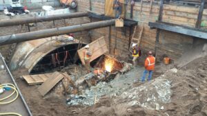
Soil nailing is an exceptionally cost-effective technique for stabilizing natural steep cuts or widening existing highways in urban corridors. Unlike conventional retaining walls that require deep excavation before building upward, soil nailing progresses strictly top-down:
- Bench Excavation: A horizontal bench is excavated 1.0 m to 1.5 m deep—the self-supporting height of the native soil for 24 hours.
- Rotary Drilling: Slender boreholes (100 mm to 150 mm diameter) are drilled at a downward inclination of 10° to 20° into the slope, typically spaced on a 1.5 m by 1.5 m grid.
- Tendon Insertion & Grouting: High-strength deformed steel bars (Grade 60 or Grade 75, typically #8 to #11 bar) equipped with centralizers are inserted. Neat cementitious grout ($w/c \approx 0.40 – 0.45$) is pumped from the bottom up via a tremie pipe.
- Shotcrete Facing & Bearing Plate: Vertical geocomposite drainage strips are placed against the raw cut face to prevent hydrostatic buildup. A steel wire mesh is pinned to the wall, followed by 100 mm of pneumatically applied fiber-reinforced shotcrete. A square steel bearing plate and hex nut are torqued onto each nail head.
3. Mechanically Stabilized Earth (MSE) Walls and High-Tenacity Geogrids
Where embankments must be constructed as fills (e.g., bridge approach ramps and highway overpasses), Mechanically Stabilized Earth (MSE) walls provide unprecedented structural ductility and height capacity (often exceeding 25 meters).
An MSE wall consists of modular precast concrete facing panels anchored to horizontal layers of high-tenacity polyester (PET) or high-density polyethylene (HDPE) geogrids buried in compacted granular backfill. Friction between the crushed stone backfill and the ribbed geogrid apertures generates immense tensile resistance, transforming the soil mass into a coherent, self-supporting gravity block capable of tolerating differential foundation settlements that would crack traditional rigid reinforced concrete walls.
4. Subsurface Drainage: The Ultimate Landslide Prevention Measure
Water management is the single most critical intervention in slope stabilization engineering. Structural reinforcement alone often fails if pore water pressures remain unaddressed. Engineers implement integrated drainage schemes:
- Sub-Horizontal Drains (Wick Drains): Perforated PVC or HDPE pipes wrapped in geotextile filter socks are drilled 20 to 60 meters deep into the mountain slope at a slight upward angle (3° to 5°). They tap into perched water tables behind the failure slip surface, depressurizing the groundwater reservoir via gravity discharge.
- Intercepting Trench Drains (French Drains): Concrete-lined crown ditches are constructed at the crest of the slope to divert surface stormwater runoff away from the vulnerable slide zone before it can infiltrate and saturate the shear plane.
5. Comparative Evaluation: Slope Stabilization Methods
The matrix below compares performance metrics across major slope stabilization engineering interventions:
| Engineering Method | Target Soil / Rock Type | Construction Direction | Relative Cost | Primary Stabilization Mechanism |
|---|---|---|---|---|
| Soil Nailing & Shotcrete | Stiff clays, silts, weathered rock | Top-Down (staged excavation) | Moderate | In-situ tensile and shear dowel resistance |
| MSE Geogrid Walls | Compacted granular structural fill | Bottom-Up (engineered embankment) | Economical | Tensile strain transfer via geogrid interlock |
| Post-Tensioned Ground Anchors | Deep failure planes, massive rock cuts | Top-Down or Bottom-Up | High | Active compressive normal prestress on slip plane |
| Micropiles (Root Piles / Reticulated) | Karst terrain, unstable colluvium | Vertical & Battered array | High | Deep shear key doweling into bedrock |
6. Rockfall Mitigation: Drapery Meshes and Dynamic Attenuator Barriers
Along steep canyon corridors where full stabilization of the entire mountain face is economically unfeasible, rockfall mitigation focuses on passive catchment:
- Pinned Drapery Wire Mesh: High-tensile steel wire mesh (such as double-twisted hexagonal wire or high-tensile steel rope mesh) is draped directly over the rock face and anchored with rock bolts. When rocks detach, the mesh prevents projectile trajectory, safely guiding falling debris into roadside drainage ditches.
- Dynamic Rockfall Catchment Fences: Erected on structural steel posts equipped with ring nets, braking friction loops, and wire rope cables. Modern barriers are certified up to 5,000 to 10,000 kilojoules (kJ) of kinetic energy impact—capable of halting a 20-ton boulder hurtling down a mountainside at 100 km/h without structural collapse.
7. Frequently Asked Questions (FAQ)
What is the fundamental difference between a soil nail and a tieback ground anchor?
Soil nails are passive structural elements installed in dense grids without initial prestressing; they only develop tensile resistance as the surrounding soil begins to deform. Ground anchors (tiebacks), by contrast, consist of multi-strand high-strength prestressing steel that is actively post-tensioned against a wall face with hydraulic jacks immediately after installation, applying large compressive normal forces across the failure surface.
Why is drainage considered more important than structural steel in slope engineering?
Water adds immense physical dead weight to the soil mass while simultaneously generating pore water pressure that pushes soil grains apart, reducing frictional shear strength to near zero. No reasonable quantity of concrete or steel can safely resist the colossal hydrostatic pressure of an undrained, saturated mountain slope. Effective drainage permanently eliminates driving hydrostatic forces at a fraction of the cost.
What is the typical design lifespan of permanent soil nail and MSE walls?
Permanent geotechnical retaining systems are designed for a 75- to 100-year design life in accordance with AASHTO and Eurocode requirements. Steel soil nails incorporate double corrosion protection (epoxy coating encapsulated inside corrugated PVC sheathing and cement grout), while MSE geogrids use durable polymers specifically formulated to resist chemical hydrolysis, oxidation, and biological degradation.
8. Summary: Building Resilient Mountain Infrastructure
Modern slope stabilization engineering transforms high-risk landslide corridors into safe, stable arteries of commerce. By synergizing deep in-situ soil nailing, resilient geosynthetic reinforcement, and gravity sub-horizontal drainage, civil engineers ensure that transportation and energy infrastructure withstand the fiercest climatic and seismic challenges.
—