Urbanization replaces natural permeable soils and forests with impervious roofs, asphalt highways, and concrete plazas. When extreme meteorological storms strike, precipitation can no longer infiltrate naturally, generating catastrophic surface runoff volumes in minutes. Modern civil infrastructure combats urban inundation through a dual paradigm: underground flood attenuation super-tunnels and nature-based Sponge City urban drainage networks.
Core Urban Hydrology Realities
- Peak Hydrograph Amplification: Urban impervious surfaces can increase peak stormwater discharge by 300% to 500% while cutting lag time (time to peak flow) by more than half compared to pre-development rural catchments.
- Subterranean Mega-Tanks: World-class megacities (such as Tokyo’s G-Cans or London’s Thames Tideway) deploy underground cavernous retention vaults and bypass tunnels to temporarily hold millions of cubic meters of storm runoff.
- Sponge City & SuDS Integration: Sustainable Urban Drainage Systems (SuDS)—including bioswales, rain gardens, permeable pavements, and green roofs—infiltrate, filter, and attenuate runoff at the source.
Table of Contents
- 1. Urban Hydrology: The Rational Method and Hydrograph Dynamics
- 2. Subterranean Super-Vaults: The Tokyo G-Cans Example
- 3. Sustainable Drainage Systems (SuDS) and Sponge City Urbanism
- 4. Smart Stormwater Networks: Automated Gate Telemetry
- 5. Frequently Asked Questions (FAQ)
- 6. Conclusion: Building Climate-Resilient Urban Water Systems
1. Urban Hydrology: The Rational Method and Hydrograph Dynamics
To engineer storm sewer pipe networks and culverts, civil engineers calculate peak design discharge ($Q$) using the classic Rational Equation:
where $C$ is the dimensionless runoff coefficient (ranging from 0.15 for grassy lawns to 0.95 for asphalt highways and concrete roofs), $I$ is rainfall intensity (mm/hr) derived from local Intensity-Duration-Frequency (IDF) curves for a chosen return period (e.g., 50-year or 100-year storm), and $A$ is catchment drainage area ($km^2$).
As cities pave over open land, $C$ increases toward 0.90+, dramatically amplifying flood peaks and overwhelming historic drainage pipes. (For how highway surfaces shed rainwater into collector systems, see our manual on Highway Drainage Architecture).
2. Subterranean Super-Vaults: The Tokyo G-Cans Example
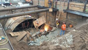
When dense urban high-rises leave zero surface land for retention ponds, civil engineers excavate monumental flood defense structures hundreds of meters below ground:
The Metropolitan Area Outer Underground Discharge Channel (G-Cans, Japan)
Located 50 meters beneath the outskirts of Tokyo, G-Cans is the world’s largest underground flood diversion system. Five colossal vertical silo shafts (each 32 meters in diameter and 65 meters deep—large enough to hold a space shuttle) intercept overflowing rivers during typhoons. Water flows through 6.3 kilometers of underground tunnels into a massive subterranean water cistern (the “Underground Temple”), supported by 59 concrete pillars weighing 500 tonnes each. Giant aviation-derivative gas turbine pumps discharge up to 200 cubic meters of water per second safely into the wide Edo River.
3. Sustainable Drainage Systems (SuDS) and Sponge City Urbanism
While subterranean vaults provide critical protection against catastrophic typhoons, day-to-day resilience is increasingly achieved through Low Impact Development (LID):
- Bioswales and Rain Gardens: Engineered vegetative depressions with engineered sandy soil media and native deep-rooted plants that slow, filter, and infiltrate runoff, removing heavy metals and suspended tire dust before groundwater recharge.
- Permeable Concrete & Porous Asphalt: Eliminates surface puddling by allowing water to drain vertically through the pavement matrix into an underlying crushed stone storage aquifer.
- Green Roofs (Living Roofs): Retain up to 70% to 90% of summer precipitation through plant uptake and evapotranspiration, insulating buildings while slashing urban heat island effects.
4. Smart Stormwater Networks: Automated Gate Telemetry
Modern stormwater infrastructure utilizes real-time Internet of Things (IoT) sensors and predictive hydrological modeling. Ultrasonic level sensors in sewer trunks communicate with AI supervisory control (SCADA) platforms. When radar meteorology forecasts a cloudburst over an urban sub-catchment, automated hydraulic slide gates and bladder dams pre-drain specific retention reservoirs hours before the storm hits, maximizing surge buffer volume.
5. Frequently Asked Questions (FAQ)
Q1: What is a “100-year storm event”?
A 100-year storm does not mean it happens only once every 100 years. It statistically means a rainfall event that has a 1% probability (1 in 100 chance) of occurring in any given single year.
Q2: What is the difference between a retention basin and a detention basin?
A detention basin (dry pond) temporarily holds storm runoff to reduce peak downstream flow and completely empties within 24–48 hours. A retention basin (wet pond) maintains a permanent pool of water year-round, treating water quality through aquatic biological processes while providing extra storage volume above its permanent pool during storms.
Q3: What causes “Combined Sewer Overflows” (CSO)?
Older industrial cities often have combined sewers where street rainwater and household toilet sewage flow through the same pipe. During torrential downpours, the water volume overwhelms the sewage treatment plant, forcing untreated sewage to overflow directly into local rivers and bays.
6. Conclusion: Building Climate-Resilient Urban Water Systems
Urban flood defense is a cornerstone of modern civil engineering. By marrying heavy subterranean hydraulic structures with decentralized, nature-based sponge infrastructure and digital telemetry, civil engineers are securing global cities against increasing climate volatility.